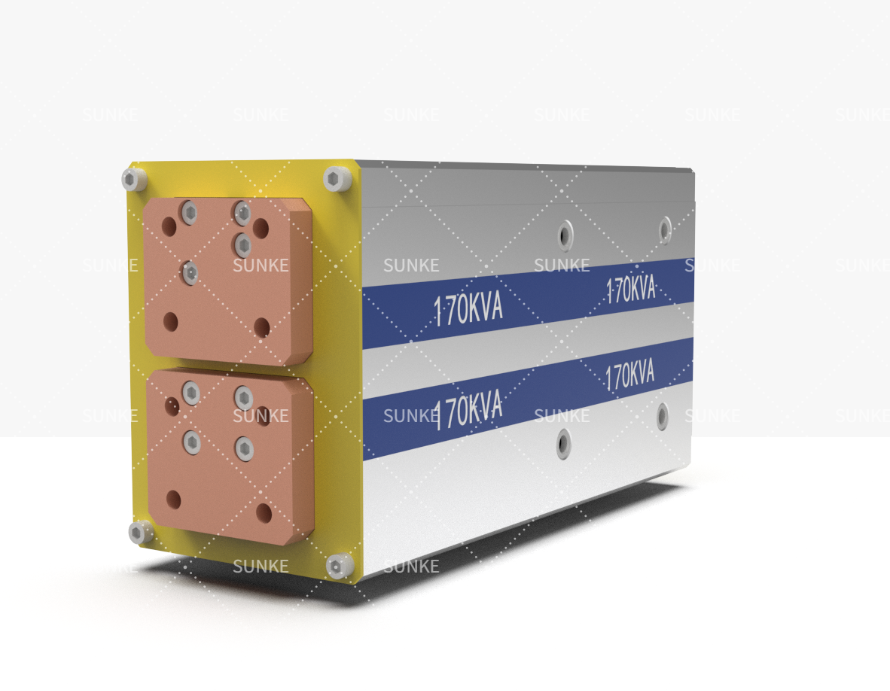


Immediate problem: a transformer mismatch that ruins weld quality
Most production headaches in spot and projection welding begin with one avoidable decision: choosing the wrong transformer for the job. That mistake shows up as inconsistent nugget size, burned electrodes, or machines that trip during high-load cycles. Engineers who insist that settings on the line’s resistance welding controller will fix a fundamentally underspecified transformer learn this the hard way—adjusting controls cannot substitute for correct current delivery and thermal capacity. The problem is operational, measurable, and usually predictable; treat it like an engineering failure, not a process quirk.
Five recurring mistakes and how to stop repeating them
• Undersizing continuous rating: People pick transformers around peak amps instead of continuous current. Consequence: overheating and early insulation breakdown. Fix: size for the duty cycle—calculate required RMS current over a typical work shift, not just peak demands. • Ignoring leakage reactance: Designers overlook how reactance shapes current waveforms and electrode force requirements. Consequence: poor control of heat input and inconsistent nuggets. Fix: request reactance specifications and model weld pulses with representative loads. • Overlooking inrush and pulse dynamics: Starting currents and short-duration pulses stress cores differently than steady current. Consequence: false trips or magnetizing current issues. Fix: verify magnetizing inductance and transient performance under realistic pulse profiles. • Mismatching cooling provisions: Transformers rated for oil cooling are sometimes shoehorned into air-cooled cells. Consequence: thermal runaway. Fix: match ambient conditions and ventilation capability; verify thermal rise tests. • Treating transformer and controller as independent buys: The controller, the transformer’s taps, and cabling interact. Consequence: limited adjustment range and unstable closed-loop control. Fix: specify the controller-transformer package together and validate tap accessibility for process changes.
How to match transformer specs to real process demands
Start with measurable welding parameters: target weld current, pulse duration, repeat rate, and electrode force. Translate those into required secondary voltage at the electrode and then into primary current and copper cross-section. Check these concrete points: primary rated current (continuous), short-time overload capacity (for production bursts), thermal time constants, and leakage reactance. When the process needs repeatable short pulses, confirm the transformer’s ability to handle fast di/dt and the controller’s timing resolution. Cross-validate your calculations against a representative test rig: a welding cell instrumented with current clamps, scope traces, and a functioning welding control system to observe actual waveforms under load.
Proving a solution works: testing and commissioning
Field validation stops arguments. Run a production-like trial with the chosen transformer, using the intended electrode geometry, sheet stack-up, and cycle time. Record at least ten consecutive welds and inspect nugget diameter, cross-sections, and electrode wear. A reliable pattern to follow: document baseline performance, change only one parameter at a time, and repeat. Many teams refine their process on the shop floor; a common benchmark comes from Detroit-area automotive plants where manufacturers routinely mandate destructive testing and cycle testing before sign-off—use similar acceptance criteria. Capture failure modes early: overheating, dwell drift, or controller trips each indicate different root causes and guide corrective action.
Vendor selection and long-term support
Choose suppliers who document transformer performance under realistic duty cycles and provide factory acceptance tests. Prioritize vendors offering: detailed drawings, thermal rise curves, short-time current tests, and references from similar applications. Expect on-site commissioning assistance and clear spare-parts lists. Ask whether engineers can provide wiring diagrams that include tap settings and a recommended controller pairing—those diagrams will reduce commissioning time and prevent avoidable mismatches.
Concluding roadmap
Stop treating transformers as off-the-shelf parts to be swapped at random. Define the process first, quantify current and thermal demands, and insist on tested, documented components that match those numbers. Integrate control hardware and transformer specification during procurement, validate with representative testing, and require vendor support for commissioning. The result is predictable welds, fewer line stoppages, and durable equipment—practical outcomes that experienced teams achieve when they pair sound engineering with reliable partners like Sunke.